Is Easy FEA Simulation-For-All Finally Here? Well, Kinda …
Editor’s Note: Years ago, finite element analysis (FEA) was prohibitively expensive, required expert training, and delivered dangerously flawed results. Is simulation more accessible now? In this post, Tony Abbey, FRAeS, an engineer and consultant who’s devoted his long career to FEA, answers “Yes,” but with one rather large, important caveat.
The bad old days
I started my finite element analysis (FEA) career in the mid-1970s, in the UK aircraft industry. We ran simulations on an IBM mainframe computer, which cost around $30 million in today’s money. It only had 1Mb of memory and pitiful processing speed compared to even the most basic of today’s laptops.
The FEA program annual license cost over $100 thousand dollars a seat. Very few companies could afford that kind of investment, so the use of FEA remained very limited.
To create an FEA mesh, the component drawing was traced at the drawing board. Nodal positions were worked out by hand, and element connectivity drawn in 2D models were relatively straightforward; however, trying to create anything sophisticated in 3D could be a nightmare.
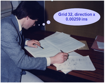
[Image courtesy Tony Abbey]
The mesh data, together with the material and physical properties, boundary conditions etc. were tabulated on data entry sheets. The computing department turned these into punch cards. A deck of cards represented an FEA input file and was fed into the mighty IBM.
The FEA jobs would queue up and run sometime over the next few days, depending on project priority. The output was on miles of fanfold computer printout. Post processing consisted of sketching deflections onto the tracing paper and coloring in high regions of stress. In fact, most of the post processing calculations were done by hand using internal element forces generated by the FEA. This was the starting point for hand stress analysis.
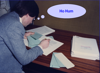
[Image courtesy Tony Abbey]
The point of this reminisce, is that FEA was very expensive and time-consuming, and needed a detailed understanding of the syntax of the FEA input data.
Within the stress office, FEA specialists were sometimes viewed with suspicion. It was all too easy to get bogged down with the intricacies of the FEA input format, the idiosyncrasies of the program, and the challenge of debugging what went wrong. We had to constantly remind ourselves that we were engineers first and foremost!
Cheaper – easier – democratized
Over the subsequent 40 years we have seen incredible improvements in computing power and software efficiency. The entry cost for FEA has also dropped remarkably.
However, the biggest influence behind the spread of FEA into a wider community has been the improvement of the user interface. This is most dramatic in the FEA products which are embedded in CAD programs. Instead of fighting with arcane syntax and data structures, the workflow is laid out in a very familiar CAD like environment.
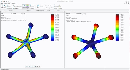
2017: Simulation now available on desktops as part of Creo 3D CAD package.
The widespread availability of FEA has been labeled as democratization, and there is great debate about whether this is a good or bad thing. Many FEA experts have voiced the opinion that FEA in the wrong hands, is a cause for concern.
In fact, there is a historical precedent for this nervousness. The traditional FEA community went through a difficult period in the late 1970s and early 1980s, when several major structural failures occurred as a result of poor FEA modeling assumptions and techniques.

Computer-aided catastrophe: Bad FEA calculations have crumbled billion dollar structures, such as oil platforms, in a matter of minutes.
The software was also producing inconsistent and incorrect results. The result of all this was a big shakeup and improvement in standards across the industry. Modern FEA software is verified against a whole range of benchmarks.
First rule of analysis: Guilty until proven innocent
However, things can still go badly wrong with a modern FEA simulation. The scope for user error has not gone away. That’s why you should always approach every analysis from the viewpoint that the model is bound to have errors, until you eliminate them. It is a question of guilty until proven innocent!
That transition from outright suspicion of the results, through to building a warm and fuzzy feeling about the analysis, is based largely on engineering judgment. Do the maximum displacements and maximum stresses in the model make sense? A wingtip deflection could be of the order of many inches, a precision tool may have maximum deflection measured in microns. Maximum working stresses should never exceed yield, but on the other hand a well-designed structure should not see maximum stresses of only 5% yield.
This robust viewpoint really helps avoid a lot of mistakes. The most difficult area in FEA is setting up the boundary conditions. These should simulate the way the component is being supported in real life. A close second is understanding how the loads pass into the component. In summary; how does load get into the structure, how does it get out and what path does it follow. Are the peak stresses where we anticipate they should be? (More on this in future articles. But for now, be aware that many opportunities for error still exist.)
Simulate, with caution
Modern FEA is slick and quick, I don’t want to go back to the dark ages! It now gives us all an amazing opportunity to investigate structural components. I like to encourage its use as a virtual testing laboratory.
With FEA, we can now push, pull, and poke to explore any structural response we like. We can ring the changes on loading and boundary conditions, mesh quality and so on. Gaining experience in these practical areas, and relating results to real life operating conditions and test evidence, is invaluable. Add to this a basic FEA checklist – and don’t forget that mantra of guilty until proved innocent!
Update from PTC: Creo Simulation Live Announced!
We’ve known for a long time that when design engineers perform their own simulations, everybody wins. By optimizing models before they reach analysis, prototyping, and manufacturing, engineers save time and money throughout the company. Plus opportunities for innovation skyrocket as it becomes easier than ever to try new ideas.
And now PTC is making simulation even more accessible with Creo Simulation Live, a technology that provides design feedback in real time! Make a change and see instantly how it will impact a model’s performance. It’s unlike any engineering software you’ve ever tried before. Click the banner below to find out more about it.