Assembly Modeling

Design engineers who manage large assemblies need the tools to help them simplify, communicate, and collaborate. Creo supports top-down and bottom-up design, along with concurrent engineering to increase productivity, reduce cost, and improve quality.

What is assembly modeling? Why is it important?

null

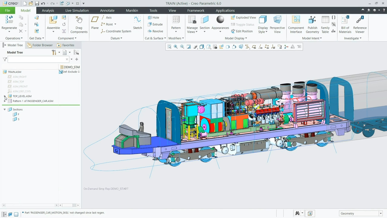
Assembly modeling involves the creation and management of multiple individual parts that come together to form a complete product or system. This is crucial for product visualization, identifying interferences, and analyzing how various components fit and interact within the assembly.

Creo helps communicate design intent, simplify assembly management, facilitate design changes, and enable team collaboration.

View Brochure
overlaycontent

Advanced assembly modeling

Top-down design

Top-down assembly modeling is an approach where the higher-level assembly guides the design of individual components. Changes are automatically propagated downstream to associated parts for design consistency.
This helps communicate design intent and manage design changes along with improving coordination, reducing errors, and streamlining the development process.
Creo Advanced Assembly Extension (AAX) facilitates top-down modeling—especially of large assemblies. AAX provides controls for change management and enables platform design for simplified management of options and variants.

Read the Datasheet

Bottom-up design

Bottom-up assembly modeling is a part-centric approach where the assembly is created by bringing together components designed by different teams.
Bottom-up modeling is well suited for projects where subassemblies can be developed in parallel or when using standard, off-the-shelf components. In addition, this can enable reuse of previously designed subassemblies.
Creo provides tools, such as Intelligent Fastener Extension (IFX), for interference detection, assembly management, and design reuse to address these challenges.

Read the Datasheet

Concurrent engineering

Concurrent engineering is a method of sharing data and design intent across design teams. System engineers set the design intent, allowing subassembly teams to work on different aspects simultaneously.
Concurrent engineering typically increases collaboration, reduces costs, and improves product quality. This fuels the collaborative culture of engaged and successful engineering teams that produce market-winning products.
Creo provides tools to enable concurrent engineering for both simple and complex projects and globally distributed teams.

Read the Blog

Benefits of assembly modeling

Whether using top-down or bottom-up design, or concurrent engineering, assembly management is a vital process for delivering high-quality, innovative products, especially with complex design work distributed across the enterprise.

<span style="background-color: #f3f3f3; color: #323b42;">Whether using top-down or bottom-up design, or concurrent engineering, assembly management is a vital process for delivering high-quality, innovative products, especially with complex design work distributed across the enterprise.</span>

Design intent control

Top-down assembly design helps communicate design intent, ensuring that components and sub-assemblies align with the overall product vision. Modifications made to the skeleton model are automatically propagated to associated components.

Top-down assembly design helps communicate design intent, ensuring that components and sub-assemblies align with the overall product vision. Modifications made to the skeleton model are automatically propagated to associated components.

Simplify large assemblies

Create simplified envelope parts to substitute for detailed design assemblies and to improve assembly performance.

Create simplified envelope parts to substitute for detailed design assemblies and to improve assembly performance.

Concurrent engineering

This approach enhances collaboration among design teams, as everyone works within the same master model, sharing geometric features, configuration rules, and other CAD data.

This approach enhances collaboration among design teams, as everyone works within the same master model, sharing geometric features, configuration rules, and other CAD data.

Visualize dependencies

View a graphical representation of interdependencies for a clear understanding of how changes will be propagated throughout the model.

View a graphical representation of interdependencies for a clear understanding of how changes will be propagated throughout the model.

Plan assembly process

Easily define and document the sequence of assembly. Color-coded models simplify assembly and service instructions.

Easily define and document the sequence of assembly. Color-coded models simplify assembly and service instructions.

Deliver configurable and customizable products

Support derivative products, build-to-order initiatives, and customization with automated input logic to change components based on user input.

Support derivative products, build-to-order initiatives, and customization with automated input logic to change components based on user input.

Creo advanced assembly extension supports business initiatives

Reduce time to market: Effectively manage distributed design teams, partners, and suppliers.

Reduce product development costs: Clearly communicate design requirements to avoid errors and late-stage scrap and rework.

Improve product quality: Effectively communicate requirements with stakeholders to create high-quality products the first time.

Lower lifecycle cost: Automate and streamline the creation of downstream deliverables, reducing assembly and service costs.

Accelerate product development: Collaborate across teams to identify new approaches and ideas.

Grow market share: Support modular design for configurable and customizable products.

Frequently asked questions

Why is large assembly performance an issue?

A large assembly in the context of computer-aided design (CAD) refers to a 3D model that consists of a significant number of components or parts, often in the hundreds or even thousands. These assemblies are typically used to design and represent complex products or systems, such as machinery, vehicles, or aerospace structures. Complex assemblies are often designed by numerous engineering teams, so it is important for teams to have visibility to design intent and changes. Large assemblies can overwhelm underpowered CAD systems and result in system crashes.

How does assembly modeling relate to PLM?

Assembly modeling and product lifecycle management (PLM) are closely related aspects of product design and development. Assembly modeling focuses on creating and managing 3D assemblies, while PLM is a comprehensive approach to managing a product's entire lifecycle, from conceptualization to disposal.

Assembly modeling is a critical component of PLM as it provides the detailed design representation of a product, which includes the individual parts and how they come together. This data is then integrated into the broader PLM system, enabling efficient data management, version control, collaboration, and the tracking of changes and revisions throughout the product's lifecycle. This ensures that assembly models are part of a seamless end-to-end product development process within the PLM framework, promoting efficiency and consistency.

What are some of the biggest challenges when using large assemblies in 3D CAD software?

When working with large assemblies in 3D CAD software, several significant challenges may arise :

  • Performance can become an issue with slower processing speeds, resource-intensive memory, and storage requirements, along with the sluggish manipulation of complex models.
  • Detecting and resolving interferences in large assemblies can be time-consuming.
  • Loading, saving, and opening such assemblies may lead to productivity setbacks.
  • Collaborative challenges emerge due to the large file sizes, making sharing and managing data among team members difficult.
  • Iterative design is hindered by slow model updates and regeneration times.
  • Effective file and data management can be complex and error prone.

What are the types of assembly modeling and what are their differences?

Top-Down Assembly

  • Top-down assembly is the design methodology starting with its highest-level framework and then gradually adding more detailed elements or components. Design intent is communicated from the top assembly down to the individual parts.

Bottom-Up assembly

  • Bottom-up assembly is a method of constructing complex structures or systems by starting with individual components and combining them to create the final product.

Concurrent Engineering

  • Concurrent engineering is an approach that emphasizes the simultaneous collaboration of multiple design teams, allowing different aspects of a project to be worked on in parallel rather than sequentially.