Lattice Structures in Additive Manufacturing: A Beginner’s Guide
With the rise of additive manufacturing (AM), more and more engineers are exploring lattice structures for their product designs. That’s because AM doesn’t constrain you to solid parts like traditional milling or mold methods.
Imagine replacing a steel bracket with an intricate web that provides ample strength, without the weight.
To help things along, CAD systems can now automate the generation of lattice structures in additive manufacturing. Today, you’re free to add patterns of beams, trusses, diamond-shaped cells, or almost any shape at all to your design—in any configuration—knowing that your 3D printer can produce these shapes.
If that sounds liberating, it is. Perhaps in ways that aren’t apparent at first.
In this post, we’ll take a closer look at these versatile structures: What they are and why you want to add them to your design repertoire. Most importantly, we introduce the nearly infinite options available to anyone who is ready to start using this new and fascinating approach to product design.
What Is a Lattice Structure?
Lattice structures are bio-inspired configurations based on repeating unit cells composed of webs or trusses with octagonal, honeycomb, or random patterns. In nature, lattice-like cell structures lend strength and flexibility to otherwise lightweight materials everywhere you turn. Think beehives, bones, or sea sponges.
Design engineers can similarly adapt lattices to their models to enhance performance. In fact, they should! Consider the following:
Lattices save weight
Whether you’re looking at a bone or an engine bracket, lattices can reduce mass without compromising stress or displacement. You can apply them to items such as lightweight structural panels, energy absorption devices, thermal insulation, ballistic protection, or porous implants.
Lattices can be self-supporting
With some lattices, you can avoid support structures normally required in additive manufacturing, saving you material as well as post-processing steps.
Lattices can be automatically generated in the CAD system
It’s no longer difficult to create these complex cells. Some CAD systems now include technology to quickly and successfully adapt these structures to your models. You specify the properties of a cell, generate it, and then test your results, all within your design environment.
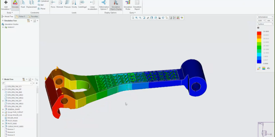
Image: A deformation study on a part with a lattice structure.
Types of Lattices
You can form a lattice in nearly infinite ways. They might be made up of random cells following the surface of a 3D model. Or they could comprise 2 1/2D extrusions or 3D beams, filling the volume of a model.
Beams and 2.5D structures make up the most common type of lattice, for example, 2 1/2D extrusions, like a honeycomb, or 3D beams, with cells composed of triangular, hexagonal, or square profiles.
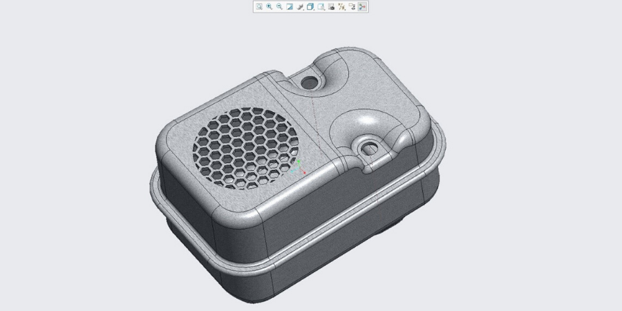
Image. A 2 1/2D honeycomb used in a part.
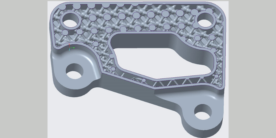
Image: A 3D lattice, beam-based, with parabolic beams, which varies in thickness from top to bottom.
Stochastic lattices use randomized cells to create a foam-like result that can conform to a bound surface. This can absorb shock and sound waves. Or fill in sandwich-type structures. In medical applications, it can even provide a structure for bone to grow in.
Formula-driven lattices are perhaps the most interesting of all. When oriented correctly, these can reduce or eliminate the need for supports. That means less material waste and less post processing. These cells may take the form of gyroids, primitives, or diamonds.
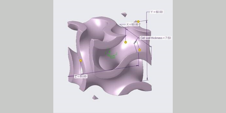
Image: A gyroid cell can be repeated to create lattices that need no support in additive manufacturing.
Custom lattices let you define your own cells. Any geometry you can model and fit into the bounds of a cube, you can turn into a lattice. This is especially useful for anyone who wants to experiment with the properties/possibilities of a lattice, whether that’s performance, endurance, fatigue. The geometry options are limited by only your imagination.
To see more about the latest advances in lattice structures in Creo, watch this video with PTC’s Paul Sagar:
Optimizing Designs That Use Lattices
Now that you’ve added a lattice to your model, you can take advantage of some powerful parametric tools to optimize it.
Representations
If you worry about complex lattices weighing your computer down, Creo can automatically create a light-weight representation while you’re working. Toggle between the full geometry, a simplified representation, or a homogenized model at any time.
What’s the difference?
A simplified representation is less precise than the full geometry, but also less demanding of your computer’s resources. It provides a good balance between performance and accuracy.
A homogenized model goes further by treating your lattice as a mathematically equivalent solid. That could be especially useful for dense lattice structures.
Many engineers use these simplified and homogenized options, for example, when they want to apply finite element analysis to their models.
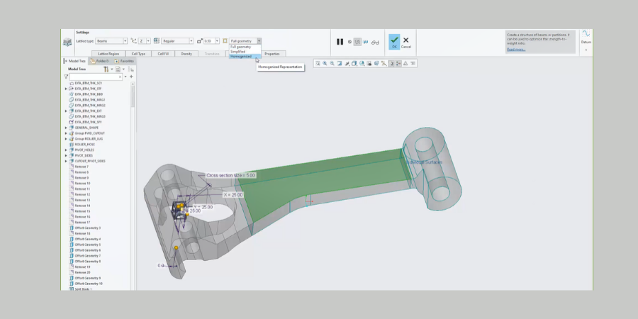
Image: The green area in this model is a homogenized lattice. It has some basic characteristics of the full model but has been averaged to improve performance temporarily.
Simulation-Driven Design
With so many options for creating lattice structures, you might wonder which choices work best for your project. The good news is that you don’t have to guess. Just design, carry out a simulation, adjust your design, simulate again, and so on--until you’ve landed on the best model that meets your requirements.
We call this simulation-driven design. You may not be used to using simulation during the design process, but it provides an excellent way to see how your design will perform with every little change.
Creo offers two options:
Creo Simulate is a traditional solver that allows you to run standard FEA on your lattice-filled model. It runs on the Creo platform, so you don’t have to jump between software packages. And remember those simplified and homogenized representations we talked about? They are perfect for getting great performance from Creo Simulate.
Creo Simulation Live can also offer FEA guidance on your design, but it works in real time. Imagine your software running structural, thermal, or modal analysis (or even CFD) within seconds during the design process—no meshing or waiting for an analyst’s report.
That means you can iterate on your design, adjusting cell types, materials, whatever—until it meets all your goals.
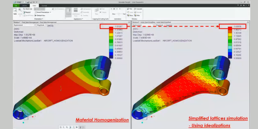
Image. Comparison of a homogenized and simplified lattice. Note the difference in deformation values. While the homogenized model performs faster, the simplified will provide more exact results.
Lattice Structure in Additive Manufacturing
Lattice types, lattice representations, lattice simulations and optimizations….Creo offers unlimited design options for using lattices in your design. Now it’s just up to you. What could you make better, stronger, faster with lattice structures?
Learn more about Creo and what’s possible with AM. Visit the Additive Manufacturing web page.